Do you want to take a high position? To become a leader is not enough ...


The ability of a metal to undergo various types of deformation is usually revealed during technological tests of samples. The results of technological tests of metals are judged by the state of their surface. If, after testing, no external defects, cracks, tears, delamination or fracture are found on the surface of the sample, then the metal has passed the test.
The extrusion test is used to determine the ability sheet metal be cold formed and drawn. I put the sample] ’into a special device in which a hole is squeezed out by a punch with a spherical surface until the first crack appears in the metal.
The characteristic of the plasticity of the metal is the depth of the hole before the destruction of the metal.
Bending test welds carried out to determine the toughness of a butt welded joint. The sample is freely mounted on two cylindrical supports and bent until the first crack appears. The characteristic of toughness is the bending angle.
A cold or hot bend test is performed to determine the ability of sheet metal to accept a specified bend in size and shape. Test pieces are cut from the sheet without surface treatment.
For sheet metal thicknesses greater than 30 mm, the bend test is usually not carried out. To carry out a bend test, press or vise is used.
The cold upset test is used to determine the ability of a metal to accept a specified compression deformation in size and shape. The tests are carried out on rods directed to the digging and intended for the manufacture of bolts, rivets, etc. The sample must have a diameter equal to the diameter of the tested bar and a height equal to two diameters of the bar. In this sample, the sample is upset by blows with a sledgehammer to the height specified by the technical conditions.
A flattening test is used to determine the ability of a strip, bar or sheet metal to accept a given flattening.
The test by winding a wire with a diameter of up to 6 mm is intended to determine the ability of a metal to withstand a given number of turns. The wire is wound onto a mandrel of a certain diameter. After winding, there should be no surface defects on the wire.
A wire bend test is used to determine the ability of a metal to withstand repeated bending and bending. Round wire and rods with a diameter of 0.8-7 mm are subjected to the test at a speed of about 60 bends per minute until the sample is destroyed. Sample length 100-150 mm.
The test for a double roof lock is designed to determine the ability of sheet metal with a thickness of less than 0.8 mm to accept deformation specified in size and shape. When tested, two sheets are connected with a double lock. The bend angle, the number of bends and unbends of the lock are indicated in the technical specifications.
A bend test of a pipe with a diameter of not more than 115 mm in a cold or hot state is needed to determine the ability of a metal to take a bend of a given size and shape. A sample pipe with a length of at least 200 mm, filled with dry sand or filled with rosin, is bent 90 ° around a mandrel, the radius of which is indicated in the technical specifications.
A pipe flattening test is necessary to determine the ability of a metal to undergo flattening deformation. A sample with a length equal to approximately the outer diameter of the pipe is flattened by blows with a hammer (hammer, sledgehammer) or under a press to the dimensions specified in the technical specifications.
To assess the ability of a material to perceive a certain deformation in conditions as close as possible to production, technological tests are used. Such assessments are qualitative in nature. They are necessary to determine the suitability of a material for the manufacture of products using a technology that involves significant and complex plastic deformation.
To determine the ability of sheet material with a thickness of up to 2 mm to withstand the operations of cold stamping (drawing), the test method for drawing a spherical dimple is used using special punches with a spherical surface (GOST 10510). The test scheme is shown in Fig. 9.3.
Figure: 9.3. Scheme of the Eriksen spherical draw test
During the test, the pulling force is recorded. The design of the device provides for the automatic termination of the drawing process at the moment when the force begins to decrease (the first cracks appear in the material). A measure of the material's ability to stretch is the depth of the elongated hole.
A sheet or tape less than 4 mm thick is tested for bending (GOST 13813). The test is carried out using the fixture shown in fig. 9.4.
Figure: 9.4. Kink test circuit
1 - lever; 2 - replaceable leash; 3 - sample; 4 - rollers; 5 - sponges; 6 - vice
The sample is bent first to the left or right by 90 0, and then each time by 180 0 in the opposite direction. The criterion for the end of the test is the destruction of the sample or the achievement of a given number of bends without destruction.
Wire made of non-ferrous and ferrous metals is tested for twisting (GOST 1545) with the determination of the number of full revolutions until the destruction of samples, the length of which is usually (- wire diameter). The bend test (GOST 1579) is also used according to a scheme similar to the test of sheet material. A winding test is carried out (GOST 10447). The wire is wound in tightly fitting turns on a cylindrical rod of a certain diameter (Figure 9.5).

Figure 9.5. Wire winding test
The number of turns should be within 5 ... 10. An indication that the specimen passed the test is the absence of delamination, flaking, cracks or tears after winding in both the base material of the specimen and its coating.
For pipes with an outer diameter not exceeding 114 mm, a bend test (GOST 3728) is used. The test consists in smoothly bending a pipe segment in any way to an angle of 90 0 (Fig. 9.6. A) so that its outer diameter does not become less than 85% of the initial one in any place. GOST establishes the value of the bend radius R depending on the pipe diameter D and wall thickness S... The sample is considered to have passed the test if, after bending, no metal discontinuities were found on it. Samples welded pipes must withstand the tests at any seam position.
The bead test (GOST 8693) is used to determine the ability of the pipe material to form a flange of a given diameter (Figure 9.6.b). An indication that the sample passed the test is the absence of cracks or tears after flanging. Flanging with preliminary distribution on the mandrel is allowed.
The expansion test (GOST 8694) reveals the ability of the pipe material to withstand deformation when expanding to a cone up to a certain diameter with a given taper angle (Fig. 9.6.c). If, after distribution, the sample has no cracks or tears, then it is considered to have passed the test.
For pipes, a flattening test to a certain size is provided (Figure 9.6.d), and for welded pipes GOST 8685 provides for the position of the seam (Figure 9.6.d), hydraulic pressure test.
To test the wire or rods of round and square cross-section, intended for the manufacture of bolts, nuts and other fasteners by the upsetting method, use the upsetting test (GOST 8817). The standard recommends a certain degree of deformation. The criterion of suitability is the absence of cracks, tears, delamination on the lateral surface of the sample.

Figure: 9.6. Pipe test schemes:
a - on the bend; b - to board; c - for distribution; d, e - for flattening
For bar materials, a bend test is widely used: bend to a certain angle (Figure 9.7.a), bend to parallelism of the sides (Figure 9.7.b), bend until the sides touch (Figure 9.7.c).

Figure: 9.7. Bending test schemes:
a - bend to a certain angle; b - bend to parallelism of the sides; c - until the parties touch
GOST 7564-97
Group B09
INTERSTATE STANDARD
RENT
General rules for sampling, blanks and samples for mechanical and technological tests
Rolled products. General rules of sampling, rough specimens and test pieces selection for mechanical and technological testing
ISS 77.040
OKSTU 0908
Date of introduction 1999-01-01
Foreword
1 DEVELOPED by the Russian Federation, the Interstate Technical Committee for Standardization MTK 120 "Cast iron, steel, rolled"
INTRODUCED by the State Standard of Russia
2 ADOPTED by the Interstate Council for Standardization, Metrology and Certification (Protocol No. 12 dated November 21, 1997)
Voted for adoption:
State name | Name of the national standardization body |
The Republic of Azerbaijan | Azgosstandart |
Republic of Armenia | Armgosstandart |
Republic of Belarus | Gosstandart of Belarus |
Georgia | Gruzstandart |
The Republic of Kazakhstan | Gosstandart of the Republic of Kazakhstan |
Kyrgyz Republic | Kyrgyzstandard |
The Republic of Moldova | Moldovastandart |
Russian Federation | Gosstandart of Russia |
The Republic of Tajikistan | Tajikgosstandart |
Turkmenistan | Main State Inspectorate of Turkmenistan |
The Republic of Uzbekistan | Uzgosstandart |
State Standard of Ukraine |
3 Standard meets international standard ISO 377-1-89, Sampling and preparation of samples and specimens of pressure treated steel - Part 1: Samples and specimens for mechanical tests"in terms of sampling and preparation of samples for mechanical tests
4 By Decree State Committee Russian Federation on standardization, metrology and certification of April 13, 1998 N 118, the interstate standard GOST 7564-97 was put into effect directly as state standard Of the Russian Federation since January 1, 1999
5 REPLACE GOST 7564-73
6 EDITION (September 2009) with Amendment (IUS 3-2002)
1 AREA OF USE
This International Standard specifies general rules sampling, blanks and specimens for tensile tests, impact bending, upsetting, cold bending from section, shaped, sheet and broad-strip rolled products.
This standard uses references to the following standards:
GOST 1497-84 (ISO 6892-84) Metals. Tensile test methods
GOST 7268-82 Steel. Method for determining the tendency to mechanical aging by impact bending test
GOST 8817-82 Metals. Draft test method
GOST 9454-78 Metals. Impact test method at low, room and high temperatures
GOST 9651-84 (ISO 783-89) Metals. Tensile test methods at elevated temperatures
GOST 11701-84 Metals. Tensile test methods for thin sheets and strips
GOST 14019-2003 (ISO 7438: 1985) Metallic materials. Bend test method
3.1 Rental unit - a product selected from a batch for the purpose of cutting out samples for making test pieces.
3.2 Try - part of the product intended for the manufacture of blanks for test specimens.
In some cases, the breakdown may be the rental unit itself.
3.3 Blank - part of the sample, processed or untreated mechanically, subjected, if necessary, to heat treatment, intended for the manufacture of test specimens.
3.4 Samples for testing - a part of a sample or workpiece of a certain size, machined or untreated mechanically and brought to the condition required for the particular test.
In some cases, the sample can be a sample or a blank.
3.5 Control state - the condition in which the sample, workpiece or test piece can be subjected to heat treatment and (or) mechanical treatment and differs from the delivery condition.
In such cases, the sample, blank, or test piece is called a control sample, control blank, or control sample.
3.6 Equivalent terms in Russian, English, French and german are given in Appendix A.
4.1 Samples, billets and samples for testing, taken in accordance with the requirements of Appendices B, C and E, should characterize the type of rolled product. Requirements for sampling, blanks and samples can be specified in other regulatory documents for hire.
4.2 Identification of samples, blanks and specimens
Samples, blanks and test specimens must be marked. If in the process of making a sample, blank and (or) sample it is impossible to avoid the removal of the marking, the transfer of the marking is performed before its removal.
4.3 The number of samples and samples taken for testing should be established in the regulatory document for rental.
4.4 When taking samples and workpieces, conditions must be ensured that protect the samples from the influence of heating and work hardening.
Allowances from the cutting line to the edge finished sample must correspond to table 1.
Table 1 - Allowances from the cutting line to the edge of the finished sample
Diameter (thickness) of rolled products, mm | Allowance, mm, with the method of cutting samples and blanks, not less |
||||
fire or heat | without heat effect |
||||
Rolled thickness |
|||||
(Amendment).
5.1 Sampling site and sample size
The sample is taken in such a way that the place of sampling and the orientation of test samples taken from it in relation to the product comply with the requirements of the rental standard or, in its absence, the requirements of Annex B.
In the event of a disagreement between the manufacturer and the consumer, samples are taken from the end of the rental at the distance given in Appendix D, unless otherwise specified in the regulatory document for rental.
The sample size must be sufficient to allow for the sampling required for the specific test.
If necessary, there should be sufficient material for retesting.
5.2 Sampling location, dimensions and orientation of test pieces
The place of sampling (sampling option) and, if necessary, the dimensions of the specimens, the orientation of the specimen in the direction of rolling (along and across) must be specified in the normative document for hire.
In the absence of such requirements, the directions specified in Appendix B.
NOTE - In order to reduce metal losses and taking into account established practice, the rolling standard, if it is technically acceptable, can regulate the possibility of using transverse samples instead of longitudinal samples (for reforged samples) in order to control the set values \u200b\u200bfor longitudinal samples.
On a test piece for impact bending, the longitudinal axis of the notch shall be perpendicular to the direction of rolling.
5.3 Sampling and preparation of samples
5.3.1 The normative document for hire shall specify whether the test is intended to determine the properties in the delivered condition (5.3.2) or in the test condition (5.3.3).
5.3.2 Test as delivered
Unless otherwise specified in the regulatory document for rolling, a sample should be taken from rolled products that have undergone all stages of plastic and (or) heat treatment to which the rolled products must be subjected before delivery.
If the sample cannot remain attached to the rental unit until the end of production (for example, sheets that are cut before annealing, samples for testing which are taken from the scrap formed during cutting), rental regulations must determine the stage of sampling from the rental unit. The processing modes to which the sample is then subjected should be similar to the processing modes of the rolled stock itself. In particular, heat treatment should be carried out in the same regimes in which rolled products are processed and, if possible, simultaneously.
Sampling should be done in such a way as not to alter the characteristics of the portion of the sample from which the samples are made.
If it is necessary to straighten a sample to obtain high-quality samples from it, straightening should be in a cold state, unless otherwise specified. Straightening is not considered machining (5.3.3.2) if it does not cause strain hardening that can change the mechanical properties of the rolled product.
NOTE After cold straightening, specimen blanks may require heat treatment. In this case, the modes of heat treatment should be determined by agreement between the manufacturer and the consumer. In exceptional cases, when straightening causes a significant change in the shape of the sample, the method of sample preparation should be established by agreement between the manufacturer and the consumer.
The sample should not be subjected to any other mechanical or thermal treatment.
5.3.3 Control state test
5.3.3.1 Sample
A sample should be taken from the product at the manufacturing stage, determined by the regulatory document for hire.
Sampling can be carried out in any way, provided that it does not entail a change in the metal.
If the method of sampling involves changes in the metal, then the sample must contain sufficient metal to exclude this influence during the manufacture of the samples. Before any heat treatment, if necessary, straightening should be done hot or cold.
5.3.3.2 The workpiece (sample), if necessary, is subjected to:
a) pressure treatment, while the regulatory documents for rolling must determine the conditions of any pressure treatment (for example, forging, rolling) to which the sample must be subjected, and indicate, in particular, the initial and final dimensions of the sample;
b) preliminary turning before heat treatment.
If the sample is to be reduced for heat treatment, then the rolling standard shall specify the dimensions to which the sample must be reduced. If necessary, the rental standard should also specify the method for reducing the sample;
c) heat treatment in an environment with guaranteed temperature stability measured by a device that has passed metrological examination.
The type of heat treatment must meet the requirements regulatory document for rolled metal products.
The workpiece should not be subjected to a given heat treatment more than once, with the exception of tempering, which can be repeated within a given temperature range. A new blank shall be selected for any retest.
For steel with a tensile strength of 1270 N / mm (130 kgf / mm) and more, specimens made with an allowance for grinding are subjected to heat treatment.
5.4 Sampling and preparation of samples for testing mechanical properties
5.4.1 Cutting and machining
The cutting of samples should be carried out in a cold way and with the adoption of precautions to avoid surface hardening and overheating of the rolled stock, which can change its mechanical properties.
Traces left by the tool after machining, which may affect the test results, should be removed by grinding (with an abundant supply of coolant) or polishing, provided that the chosen surface finishing method maintains the size and shape of the sample within the tolerances specified in the standard for the corresponding test.
5.4.2 The shape, dimensions and permissible deviations in the dimensions of the samples must comply with GOST 1497, GOST 7268, GOST 9454, GOST 9651 and GOST 11701.
5.4.3 For tensile testing of long products of round, square and hexagonal profiles, cylindrical samples are used.
5.4.4 For tensile testing of strip and sheet products up to 25 mm thick, flat samples are used, over 25 mm - cylindrical samples. Testing of rolled products with a thickness of 7-25 mm can be carried out on both flat and cylindrical samples. The quality document indicates the type of sample.
5.4.5 For testing shaped rolled stock with a thickness of up to 25 mm inclusive, flat samples are used with the surface layers of the rolled metal preserved on them, and with non-parallel sides of the shelf - with the preservation of the surface layers of the rolled stock on one side; if the thickness of the rolled stock is more than 25 mm, it is allowed to process a flat sample up to a thickness of 25 mm while retaining the rolled surface on one side of the sample or making cylindrical samples.
Note - When the thickness of the profile flange is from 7 to 25 mm, the test can be carried out both on flat and on cylindrical samples.
5.4.6 Rolled round, square and hexagonal sections, for which the selection of blanks and samples is carried out according to option 1, with a diameter or side of a square up to 25 mm, strip products up to 25 mm thick and up to 50 mm wide, shaped profiles with a shelf thickness up to 4 mm can be tensile tested on specimens that have not been machined.
5.4.7 For impact bending testing of rolled products with a diameter of up to 16 mm inclusive, square with a side of a square up to 10 mm inclusive and strip and sheet products with a thickness of up to 10 mm inclusive, samples of 5x10x55 mm are used, for rolled products with a diameter of more than 16 mm and a thickness of more than 10 mm - samples 10x10x55 mm in size.
5.4.8 Samples for impact bending test from shaped stock are cut in such a way that one of the side faces coincides with the rolled surface. The notch axis should be perpendicular to the rolled surface.
5.4.9 In the case of heat treatment of samples, the requirements should be the same as for blanks (5.3.3.2, subparagraph c).
6.1 Samples for upsetting tests are taken from either end of the bar or strip. For rolled products supplied in coils, a sample is taken at a distance of at least 1.5 m from the end with a coil mass of up to 250 kg and at a distance of at least 3.0 m - with a coil mass of more than 250 kg.
6.2 Test conditions, surface condition of samples and procedure for evaluating the results must comply with the requirements of GOST 8817.
7.1 Place of cutting of samples in relation to the direction of rolling and the length of the rolled - in accordance with Appendix B.
7.2 When taking samples and blanks, conditions must be provided that protect the samples from the effects of heating and work hardening, set forth in 4.4 of this standard.
7.3 The minimum distance from the end of the product for sampling or samples for testing in case of disagreement is in accordance with Appendix D.
7.4 Sampling scheme for cold bending tests - in accordance with Appendix D.
7.5 Methods of sampling, types of samples and other requirements for cold bending testing must meet the requirements of GOST 14019.
APPENDIX A
(reference)
Table A.1 - Equivalent terms
Designation | Clause of the standard |
||||
russian | english | french | german | ||
Rental unit | Produit echantillon | ||||
Blank | Rough specimen | ||||
Sample for testing | |||||
Figure A.1
Table B.1 - Place of cutting of samples, blanks and samples
Rental type | Position of the longitudinal axis of the sample in relation to the rolling direction | Place of cutting of samples, blanks and samples along the length |
High-quality round, square, hexagonal and rectangular sections | From either end of a bar or skein. For rolling in coils, samples are taken at a distance of at least 1.5 m from the end with a coil mass of up to 250 kg and at a distance of at least 3.0 m with a coil mass of more than 250 kg |
|
Shaped (U-sections, T-bars, corner, Z-beams, I-beams, wide-flange beams, a special interchangeable profile for support of mine workings - SVP) | From either end |
|
Sheet, roll, broadband up to 600 mm wide, incl. after longitudinal dissolution | |
|
Sheet, roll, broadband 600 mm and more | From any end of sheet and broadband products. For rolled coils at a distance of at least 1 m from the end of the coil |
|
Note - For broadband rolled products with a width of 600-1000 mm, by agreement between the manufacturer and the consumer, it is allowed to use longitudinal samples. |
||
B.1 Scheme for taking billets from samples to determine the mechanical properties of rolled products in the delivery state (option 1)
B.1.1 Sampling of billets from samples from long products
______________
Figure B.1 - Schemes of sampling of billets from samples from rolled products of circular and polygonal cross-sections
______________
* It is allowed to make a selection before 01.01.2001.
Figure B.2 - Schemes of sampling of billets from samples from rolled square and rectangular sections
Strip with beveled edges
Figure B.3 - Schemes for sampling blanks from a strip with beveled edges
(Amendment).
B.1.2 Sampling of blanks from samples from shaped rolled products *
_____________
* For unequal angles, the workpiece is cut from the larger flange.
Figure B.4 - Schemes of sampling of billets from samples from structural shapes
B.1.3 Sampling from sheet and broadband products
Rolled width; and - sampling site
Figure B.5 - Schemes of sampling from sheet and broadband products
Table B.1 - Position of the sample relative to the rolled surface
Test type | Rolled thickness, | The position of the longitudinal axis of the sample in relation to the direction of rolling with the width of the rolled product, mm | Sample position relative to the surface, mm |
|
150<<600 | ||||
Tensile at normal temperature | ||||
Control of the yield point at elevated rolling temperatures for products working under pressure | From 3 | Across, next to the tensile test piece at normal temperature | ||
Impact bending | From 5 | |||
Across or along in accordance with the standard or TU for hire | ||||
Rolled thickness | ||||
Note - By agreement between the manufacturer and the consumer, it is allowed to use: |
||||
B.2 Scheme of sampling of billets from samples to determine the mechanical properties of rolled steel from the improved steel in the delivery condition (normalized or improved) or in the control condition (option 2)
B.2.1 Sampling of billets from samples from long products
Rolled round and polygonal sections
Figure B.6 - Schemes for the selection of billets from samples from rolled products of circular and polygonal cross-sections
Rolled square and rectangular sections
Figure B.7 - Schemes for the selection of billets from samples from rolled square and rectangular sections
B.2.2 Sampling of blanks from samples from a strip with beveled edges of sheet and broad-strip products - similar to option 1
Table D.1 - Minimum distance from the end of the product for sampling, blanks and samples
Rental type | Minimum distance from the end of the product |
|||
Rolled products in coils with rolled ends, diameter *, mm: | ||||
Rolled in bars | ||||
Rolled in rolls with rolled ends | 1 turn, but not more than 2 turns from the outer end of the roll |
|||
Rolled in rolls with hardened and tempered ends | 0.5 x roll diameter, but not less than 160 mm |
|||
Sheets with fired or cold cut ends | ||||
* For rolled square and hexagonal sections, the diameter of a circle is taken, the cross-sectional area of \u200b\u200bwhich is equivalent to the cross-sectional area of \u200b\u200ba square or hexagon. |
||||
E.1 Sampling from long products
Rolled round and polygonal sections
Figure E.1 - Schemes of sampling from rolled products of round and polygonal cross-sections
Rolled square section
Figure E.2 - Scheme of sampling from rolled square section
Rolled rectangular section
Figure E.3 - Schemes of sampling from rolled rectangular section
E.2 Sampling from structural shapes *
_____________
* For unequal corners, samples are taken from the larger shelf.
Figure E.4 - Schemes of sampling from structural shapes
E.3 Sampling from sheet and broadband products - anywhere in width for rolled thickness:
Figure E.5 - Schemes of sampling from sheet and broadband products
Electronic text of the document
prepared by Kodeks JSC and verified by:
official publication
Ordinary carbon steel
quality and low-alloy: Sat. GOSTs. -
M .: Standartinform, 2009
Carrying out technological tests is a necessary operation to confirm the correctness of the chosen design of the bimetallic product and the composition of the alloys.
For each type of rotary-type crushing equipment, there are several schemes for carrying out technological tests, which have the corresponding advantages and disadvantages.
For those types of equipment that have massive working bodies (more than 30 kg) and uniform horizontal wear along the rotor, if the physical and mechanical properties of the crushed raw material are comparable and the volumes of its processing are clearly reflected in the operational logs, technological tests do not pose a particular problem. These types of equipment include all impact and centrifugal crushers, as well as most types of hammer crushers. In this case, technological tests can be carried out in truncated volumes, on incomplete sets of working bodies.
If there are zones of increased horizontal (usually lateral) or vertical wear in hammer crushers (Fig. 1), which is usually typical for hammer crushers with hammers weighing less than 30 kg, in case of unsatisfactory results, the most optimal boundary between the bimetallic layers is selected, or, if necessary, the design of the entire product changes with a change in the pouring border from horizontal to inclined (Fig. 2), which completely protects the working plane, both from vertical wear and from the ingress of metal objects. In such cases, technological tests can be carried out several times until the desired result is obtained.

fig. 1 Various types of local wear: 1 - intense lateral wear; 2 - intense vertical wear. In both cases, the softer steel is subject to more significant wear.


fig. 2 Changing the design of a bimetallic product: from a horizontal line of articulation of alloys (1), to an inclined (2), completely protecting the working plane, both from vertical wear and from the ingress of metal objects.
The most difficult, due to the design features of the equipment, are technological tests carried out on hammer mills, in most cases with uneven horizontal wear.
This is facilitated by the following factors:
Tangential hammer mills (MMT) are closed-type crushing equipment (Fig. 3), with a system of return to the grinding chamber of under-ground material from the separator from the sides, which creates extreme wear zones on the outer rows of the rotor, with complete wear of the lugs and the occurrence of emergency situations from for flying them off the bearers. (Fig. 4)

Fig. 3

Fig. 4 Photo of intensive wear of the beater on the side rows
In addition to the side zones of intense wear caused by the design features of the equipment, zones of intense horizontal wear are very often added, caused by the uneven flow of coal into the grinding chamber (Fig. 5)
 fig. 5
 Uneven coal supply contributes to the formation of an uneven wear contour of the beaters (Fig. 6), which in turn contributes to such a negative, but quite understandable action of technical personnel striving to reduce the risks of emergencies, as to change of beaters with an uneven profile (Fig. 7). still quite high residual service life.
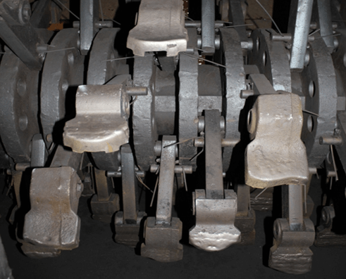 fig. 6
 fig. 7
 fig. 8
An additional difficulty in adjusting the coal supply to the grinding chamber is introduced by such an external factor as the low quality of cast beams made of manganese steels, first of all, the presence of different sized pores and voids in the working section, leading to the formation of an uneven wear profile (Fig. 8), even in in case of uniform coal supply.
Due to the fact that the design features of the grinding chamber allow the formation of lining surfaces of various configurations, the aerodynamic characteristics inside the chamber cavity differ not only in machines at different industrial facilities, but sometimes even within the same boiler-turbine shop. Also, the perforation of the disks makes it possible to fix on them a different number of beaters - 3, 4, 6, 8 and to form a different number of beats in the mill along the rotor, which also significantly affects the nature of dynamic flows.
There are three schemes for conducting technological tests of new beats, each of which has its own advantages, disadvantages and methods of compensation for these disadvantages.
| Options | Weight schemes | ||
| Full | Half | Alternating | |
| Schematic representation |  |
 |
 |
| Advantages | Test conditions are closest to operating conditions. | Commensurate loads, the same coal quality. Short test times. | |
| disadvantages | Unreliability of data due to incommensurability of loads and quality of coals in the absence of means of individual control over a specific MMT. Duration of testing. | Inaccurate data in case of uneven horizontal wear; The occurrence of the rotor beating as a result of different wear rates of different groups of beats. | Inaccurate data due to increased wear of more wear-resistant blows that take on an increased load. |
| Compensation methods for deficiencies | Statistical. Increased confidence through more tests and comparisons with a statistically defined comparison basis (average operating period). | The risk of emergencies due to rotor beating cannot be eliminated. Inaccuracy of data due to uneven horizontal wear is eliminated by alternating loading of the same parts with different groups of beats. | no |
Technological tests are very diverse. They only serve quality or comparative metal evaluations.
Usually, a technological sample is subject to technical specifications. As a rule, sample sizes and test conditions should be strictly the same, only in this case the results can be compared.
As indicators of the suitability of the metal for each type of sample, its characteristics are selected. Such characteristics can be the bending angle, the degree of reduction, the number of bends in the wire before the first signs of destruction appear, the degree of upsetting, etc.
Here are the following technological samples as examples:
It is shown schematically in the figure:
Bending can be done up to a certain angle, or until the sides are parallel, or until the sides touch. The metal that withstands the sample must not have cracks.
Such a test determines the ability of the metal to take a bend of a given size and shape.


Cold sludge sample(Fig. 31) allows you to determine the ability of a metal to undergo compression deformation of a given size and shape.
The sample is considered to have withstood the sample if, when up to a specified height, h no cracks or fractures appeared in it.

Cold and hot pipe bend test (fig. 32) reveals the ability of the pipe metal to take a given bend in size and shape. The test consists of bending a 90 "length of pipe filled with dry sand or rosin around a mandrel.
After bending, the pipe should not have:
volosovin,
tears,
bundles.

Wire bend test is performed to determine the ability of the wire to withstand repeated bending (Fig. 33).
The number of bends to break indicates the metal's ability to withstand multiple kinks.

Wire winding test(fig. 34).
Do you want to take a high position? To become a leader is not enough ...

If your web pages take a long time to load or your YouTube videos are slow ...

The online keyboard simulator is a touch typing training service right from ...