A general indicator characterizing the use of fixed assets on...


The main differences between plasma metallization and other melting methods are higher temperature and greater power, which provides a significant increase in process productivity and the ability to apply and melt any heat-resistant and wear-resistant materials (Fig. 4.8). For plasma spraying, argon and nitrogen gases are used to provide the jet temperature. For plasma metallization, UPU and UMN installations are widely used, the set of which includes a rotator, a protective chamber, a powder dispenser, a power source and a control panel.
The main part of the installation is the plasmatron, the service life of which is determined by the durability of the nozzle. The operating period of the plasma torch is short, so its wearing parts are made replaceable. The current sources are welding generators PSO-500 or rectifiers I PN-160/600.
Rice. 4.8. Scheme of the plasma spraying process:
1 - powder dispenser; 2 - cathode; 3 - insulating gasket; 4 - anode; 5 - transport gas; 6 - coolant; 7 - plasma-forming gas
Argon or less scarce and cheaper nitrogen is used as a plasma-forming gas. However, igniting an arc in a nitrogen environment is more difficult and requires significantly higher voltage, which poses a danger to operating personnel. A method is used in which an arc is ignited in an argon environment with a lower excitation and arc burning voltage, and then switched to nitrogen. The plasma-forming gas is ionized and leaves the plasmatron nozzle in the form of a jet of small cross-section. The compression is facilitated by the walls of the nozzle channel and the electromagnetic field that arises around the jet. The temperature of the plasma jet depends on the current strength, type and flow rate of gas and varies from 10,000 to 30,000 °C; gas flow speed is 100-1500 m/s. Argon plasma has a temperature of 15,000-30,000 °C, nitrogen plasma - 10,000-15,000 °C.
In plasma metallization, granulated powder with a particle size of 50-200 microns is used as the applied material. The powder is fed into the arc zone by a transport gas (nitrogen), melted and transferred to the part. The flight speed of powder particles is 150-200 m/s, the distance from the nozzle to the surface of the part is 50-80 mm. Due to the higher temperature of the applied material and the higher flight speed of the sprayed particles, the strength of the connection between the coating and the part in this method is higher than with other metallization methods.
Plasma metallization, which occurs at a high temperature of the plasma jet, makes it possible to apply any material
materials, including the most wear-resistant ones, but this raises the problem of subsequent processing of super-hard and wear-resistant materials.
The use of pulsed laser radiation, the duration of which is milliseconds, makes it possible to obtain minimal thermally affected zones that do not exceed several tens of microns. Minimum volumes of melt and minimal heat input into the part being welded make it possible to reduce longitudinal and transverse deformations and thereby maintain the precision dimensions of the part within the tolerance range of several microns. The precision of guidance and local action of the laser beam allows welding strictly defined geometric areas of the part, providing a minimum allowance for machining, which is 0.2-0.5 mm. Since during pulsed laser cladding the heat-affected zones are very small, the substrate remains practically cold, and the cooling rate of the liquid phase of the metal melt reaches 102-103 °C/s. Under these conditions, an auto-hardening process takes place, which leads to the formation of an extremely finely dispersed structure with increased wear resistance.
When compared, almost all of the fundamental technical differences between electric arc cladding and pulsed laser cladding technologies are a consequence of the fact that the arc is a concentrated welding energy source, and the laser beam is a highly concentrated energy source. Pulsed laser cladding compared to electric arc cladding is characterized by minimum volumes melt, heat-affected zones and, accordingly, significantly less transverse and longitudinal shrinkage.
After electric arc surfacing, allowances can reach several millimeters, which necessitates subsequent machining. The use of an electric arc as an energy source is accompanied by its forceful effect on the liquid phase of the metal melt, resulting in the formation of undercuts that do not occur during laser cladding. Electric arc surfacing requires preliminary and concomitant" heating of the welding areas and subsequent heat treatment and "and type from laser surfacing.
Laser surfacing technology can be used to restore worn-out molds, dies and eliminate various defects formed during the manufacturing process of molds and dies. Types of defects eliminated using laser cladding: HRC hardness test sites, cracks, nicks, scuffs, cavities and pores, deep cracks, adhesive bonding sites. Technological process Laser surfacing is the simultaneous supply of laser radiation and filler wire to the defect site in an environment of inert gases. The filler material, melting, fills the defect site. After laser cladding, minimal cladding is required compared to traditional cladding methods. mechanical restoration. The high accuracy of pointing the laser beam at the location of the defect, the locality of the action of laser radiation makes it possible to fuse strictly defined areas of defective parts (Fig. 4.9).
![]()
 The short duration of the process, the duration of the laser pulse of several milliseconds, as well as the precise dosage of energy ensure minimal heat-affected zones and the absence of part wear. Laser surfacing can significantly reduce the labor intensity of tooling repairs and, as a consequence, the cost by eliminating from the process preheating, subsequent heat treatment, and the need to remove the chromium coating from the surface and its subsequent application if the part is chrome-plated. The advantages of laser cladding are listed in table. 4.2.
To prevent oxidation of the molten metal, the surfacing zone is protected with inert gases, for example, a mixture of argon and helium. For surfacing large-sized components (up to several meters in length), solid-state laser systems equipped with fiber optic systems are used. A technology has been developed for eliminating defects in the form of hot and cold non-through cracks formed during electric arc welding with stick electrodes using pulsed laser radiation from solid-state lasers.
Welding several cracks using pulsed laser radiation makes it possible to implement the so-called “cold” welding mode, in which the weld seam of the repaired area does not heat up, which allows saving mechanical strength welded joint and avoid tempering of metal in the weld.
The use of a fiber optic system several meters long allows repairs to be carried out in the most difficult-to-reach places. This technology can be used to eliminate various defects formed during electric arc welding - cracks, both cold and hot, cavities, craters, fistulas, undercuts.
Due to the nature and operating conditions, the lateral surface of high-pressure turbine blades is subject to microdamage from mechanical, chemical and thermal influences. Damageability analysis shows that about 70% of their total number are parts with surface defects up to 0.4-2.0 mm deep. The use of fiber optic systems for delivering a laser beam to the defect site opens up the possibility of repairing a turbine blade without dismantling it. The size of the thermally affected zone does not exceed 15 µm. The structure of the deposited layer is finely dispersed.

Rice. 4.11. Cross section in the place of unsoldered pipes of the refrigerator section
 |
|||
Rice. 4.12. Grinding of the defect site processed in welding-soldering mode
During the manufacturing process of water sections, defects in the form of missing solders may occur. A technology has been developed to eliminate section leaks using pulsed laser soldering-welding (Fig. 4.11 and 4.12).
To eliminate leaks in a soldered seam, pulsed laser radiation from a solid-state laser is used. A television system built into the laser emitter using target designation based on a He - Ne (helium - neon) laser allows you to accurately direct the laser beam to the defect site. Equipping the laser with a fiber optic system allows you to eliminate defects in hard-to-reach places and make a quick transition from one defect to another.
Production metal products modernized as advanced technologies develop. Metal is more susceptible to moisture, therefore, to ensure a long service life and give parts, working mechanisms and surfaces the required properties, metal spraying is widely used in modern industry. Powder processing technology consists of applying a protective layer to the base metal base, which provides high anti-corrosion characteristics of the sprayed products.
After powder treatment, the metal surface acquires important protective properties. Depending on the purpose and area of application, metal parts are given fireproof, anti-corrosion, and wear-resistant characteristics.
The main purpose of spraying a base metal base is to ensure a long service life of parts and mechanisms as a result of exposure to vibration processes, high temperatures, alternating loads, influence of aggressive environments.
Metal sputtering processes are performed in several ways:
The technological method for spraying parts, mechanisms, and metal surfaces is selected depending on the characteristics that need to be imparted to the sprayed base. Since the method of volumetric alloying is economically expensive, advanced technologies of laser, plasma, and vacuum metallization are widely used on an industrial scale.
Metallization of surfaces using magnetron sputtering technology is based on melting the metal from which the magnetron target is made. The treatment occurs in the process of impact action by ions of the working gaseous medium formed in the discharge plasma. Features of using magnetron installations:

The advantages of magnetron sputtering make it possible to use this processing technology to obtain thin films of metals. For example, aluminum, copper, gold, silver products. Semiconductor films are formed - silicon, germanium, silicon carbide, gallium arsenide, as well as the formation of dielectric coatings.
The main advantage of the magnetron method is the high speed of target sputtering, particle deposition, and reproduction accuracy chemical composition, no overheating of the workpiece, uniformity of the applied coating.

The use of magnetron equipment for sputtering makes it possible to process metals and semiconductors with a high rate of particle deposition, to create thin films with a dense crystalline structure and high adhesive properties on the sputtered surface. The main list of works on magnetron metallization includes chrome plating, nickel plating, reactive sputtering of oxides, carbon and oxynitrides, and high-speed surfacing of copper.
To obtain multi-micron coatings on metal products, the ion-plasma sputtering method is widely used. It is based on the use of a vacuum environment and the physicochemical properties of materials to evaporate and disperse in airless space.
The technologically complex process makes it possible to solve important technical problems for metallization of products using an ion-plasma sputtering installation:

The process of ion plasma sputtering is based on the use of a vacuum environment. After ignition of the cathode, spots of the first and second levels are formed, which move at high speed and form a plasma jet in the ion layer. The jet obtained as a result of eroding the cathodes passes through a vacuum environment and interacts with condensed surfaces, depositing a densely crystalline coating.
The use of ion-plasma sputtering makes it possible to apply protective coatings at cathode ignition temperatures of up to 100°C, and is distinguished by a fairly simple scheme for obtaining layers up to 20 microns thick.

With the help of ion-plasma sputtering on metal, it is possible to impart the required properties to structurally complex products of non-standard geometric shapes. After processing, the metal surface does not need to be coated with a finishing layer.
Along with ion-plasma sputtering and magnetron methods of metal processing, another method is used - plasma metallization. The main objective of the technology is to protect products from oxidative processes in aggressive environments, improve performance, harden the treated surface, and increase resistance to mechanical loads.
Plasma spraying of aluminum and other metals is based on high-speed acceleration of metal powder in a plasma flow with the deposition of microparticles in the form of a coating layer.

Features and advantages of metal plasma spraying technology:
The main components of the working installation are a high-frequency generator, a sealing chamber, a gas medium tank, pumping unit for supplying pressure, control system. It is possible to use plasma spraying technology on metal at home if you have the necessary equipment with a vacuum chamber - exposure to oxygen leads to oxidation of hot metal surfaces and the target.
On video: restoration of parts by spraying.
Metal surfacing laser method allows you to restore parts and mechanisms with light streams generated from optical-quantum equipment. Vacuum laser deposition is one of the most promising methods for producing nanostructured films. The process is based on sputtering a target with a light beam followed by deposition of particles on a substrate.

Advantages of the technology: ease of implementation of metallization, uniform evaporation of chemical elements, production of film coatings with a given stoichiometric composition. Thanks to the narrow directionality of the laser beam at the place where it is concentrated, it is possible to obtain surfacing of the product with any metals.
Mechanisms of formation of liquid-droplet phases:
If in a laser installation, when surfacing metals onto a target, all three mechanisms of the working process (hydrodynamics, vaporization, high-frequency pulse) operate simultaneously, the acquisition of the required characteristics by the product depends on the magnitude of the influence of the specific surfacing mechanism.
One of the conditions for high-quality laser processing is exposure of the target to such an irradiation mode that the output is laser torches with the smallest inclusion of liquid-droplet particles.

There are two options for protecting metals from the negative effects of external and working factors - alloying and sputtering with vacuum equipment. That is, atoms of chemical elements are added to the alloy, giving the products the required characteristics, or a protective coating is applied to the base surface.
Most often in the metallization industry they use the technology of applying galvanic coatings, use methods of immersing parts in the melt, use a vacuum environment in processing processes, and use magnetron equipment.
Sometimes detonation gas spraying is used, which accelerates particles to incredible speeds. Plasmatrons, electric arc metallization, gas-flame processing, and ion sputtering are widely used. Industry challenges dictate their conditions, and engineers have faced the need to create inexpensive, easy-to-use equipment that can use the properties of heated compressed air.
The concept of powder metallization appeared with the addition of finely dispersed ceramics or particles to the metal powder hard metal. Used to work with aluminum, nickel, copper.

The results of the experiments exceeded expectations, allowing us to solve the following problems:
Thanks to the successful work of engineers, it was possible to create a portable device that allows metallization of coatings on all industrial enterprises and at home. Requirements for successful work equipment - the presence of a compressor unit (or air network) with a compressed air pressure of five to six atmospheres and power supply.

The table below shows data for chrome plating aluminum at home. Before applying galvanic coating, it is necessary to “put” an intermediate metal layer on the part, and then spray aluminum.
Table 1. Chrome plating of aluminum

The use of advanced equipment for metallization of products makes it possible to solve technical issues related to increasing anti-corrosion, strength, and performance characteristics, as well as giving machines, parts and mechanisms the required properties for operation in difficult operating conditions.


So, what is the principle of plasma spraying? In all plasma spraying devices, the powder acquires temperature and speed in a stream of hot gas created by a plasmatron. In turn, a plasmatron or plasma generator is a device invented in the 1920s, in which an electric arc burning between the cathode and anode in a limited volume (nozzle) is inflated with an inert gas and creates a torch of high-temperature reduction flame.
Why is this principle so attractive for solving thermal spraying problems? Precisely because the plasmatron flame is very hot and always strictly reducing; the presence of oxygen in the plasmatron is strictly prohibited due to the rapid, otherwise, destruction of electrode materials (the partial pressure of oxygen in plasma-forming gases is determined by their purity and should not be higher than 0.004%). The flame torch of a plasmatron, when used correctly, can not only restore the active metal surface from oxide films on sprayed particles, but even clean the surface of the substrate itself from oxides. This opportunity is provided exclusively by the plasma spraying method.
Regarding plasma spraying, there are a number of prejudices among theorists and practitioners of thermal spraying, which, in most cases, are associated not with the process as such, but with a misunderstanding of the essence of the spraying process, design flaws of specific devices and their incorrect use. Let's discuss these prejudices:
1.“The plasma flame is too hot and therefore suitable only for sputtering refractory metal and oxide materials. ceramic materials. Too high a temperature leads to evaporation of part of the powder and destruction of chromium and tungsten carbides.”
Indeed, the plasma temperature can reach 20,000°C or more, which is much higher than, for example, the temperature of an oxy-acetylene flame (about 3000°C). However, the flame temperature has very little to do with the temperature of the sprayed particles. Without delving into the physics of the interaction of hot gas with solid particles, we will only say that this interaction is very complex and depends on a large number of parameters, including not only the temperature of the gas, its speed, the length of the torch and the size of the particles, but also the chemical compositions of the gas and particles . In addition, it is not the absolute temperature of the flame, but its luminosity, that is decisive for the transfer of heat from the torch to the particles. For example, a hotter but almost invisible hydrogen-oxygen flame heats particles much worse than a cooler but brighter (due to glowing carbon nanoparticles) acetylene-oxygen flame. The luminosity of a plasma plume depends on the composition of the plasma-forming gas and on the size and composition of particles passing through it. It is interesting that in many cases this luminosity is less than that of an oxygen-acetylene flame and it has to be increased in various ways just to give the particles at least the minimum required temperature. Since the flame length of gas-flame devices also often exceeds the length of the plasma torch, a “paradox” results: coarse-grained metal powders heat up more strongly in powder flame spray devices than in more powerful and “hot” plasma spray devices.
2. “Particle velocity during plasma spraying is not sufficient to produce dense coatings.”
The flow rate of gas and particles in it is determined not by the principle of flame formation, but solely by the design of the device. Currently, there are industrial plasma spraying devices with a Laval nozzle that provide particles with supersonic speed.
3. “Only expensive vacuum plasma spraying units are suitable for metal spraying, while atmospheric plasma spraying units are unsuitable due to the oxidation of metal particles.”
Strangely enough, one hears such a statement quite often, even from people who are practically involved in plasma spraying, especially in relation to MCrAlY coatings for blades gas turbines. In fact, in this statement there is a typical substitution of concepts: purely metal coatings from low-melting nickel alloys obtained by vacuum plasma spraying (VPS) are indeed better than atmospheric spraying (APS), but not due to the oxidation of particles in the plasma, but completely another reason, which will be discussed in the section on vacuum plasma spraying. The oxidation of metal particles in both of these methods occurs in the same way.
Atmospheric plasma spraying devices are no different from vacuum plasma spraying devices. The difference is not in the devices themselves, but in the way the deposition process is organized: atmospheric deposition is carried out in air, but with vacuum deposition both the plasmatron and the part being sprayed are in a vacuum chamber under vacuum. It is clear that atmospheric deposition is much more accessible and cheaper than vacuum deposition; moreover, for large parts, vacuum deposition becomes simply impossible due to the unrealistic size of the vacuum chamber. The plasmatrons themselves can be used for both atmospheric and vacuum deposition.
To more clearly explain the features of plasma spraying, let’s move on to consider the different designs that exist today.
Plasma spraying devices come in a wide variety of designs. We will consider them from the most “traditional” to the most “advanced”.
The most common devices are those with one cathode and one anode, and with the powder introduced outside a short nozzle, perpendicular to the flame axis.
The operating principle of such devices is shown in the diagram (Figure 28):
Rice. 28. The principle of plasma spraying.
As can be seen from the diagram, the short nozzle of the plasmatron is also an anode. The powder is introduced outside the nozzle perpendicular to the flame axis, in close proximity to the arc.
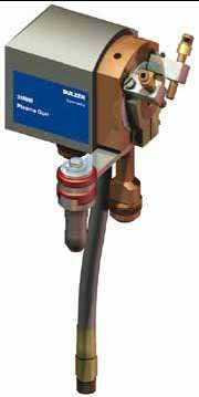
The most popular device of this type is the 3MB plasmatron from Sulzer Metco, which, with minor modifications, has been around for more than 40 years. Figure 29 shows the current models of this series with a maximum power of 40 kW.
Rice. 29. Plasmatron 3MB.

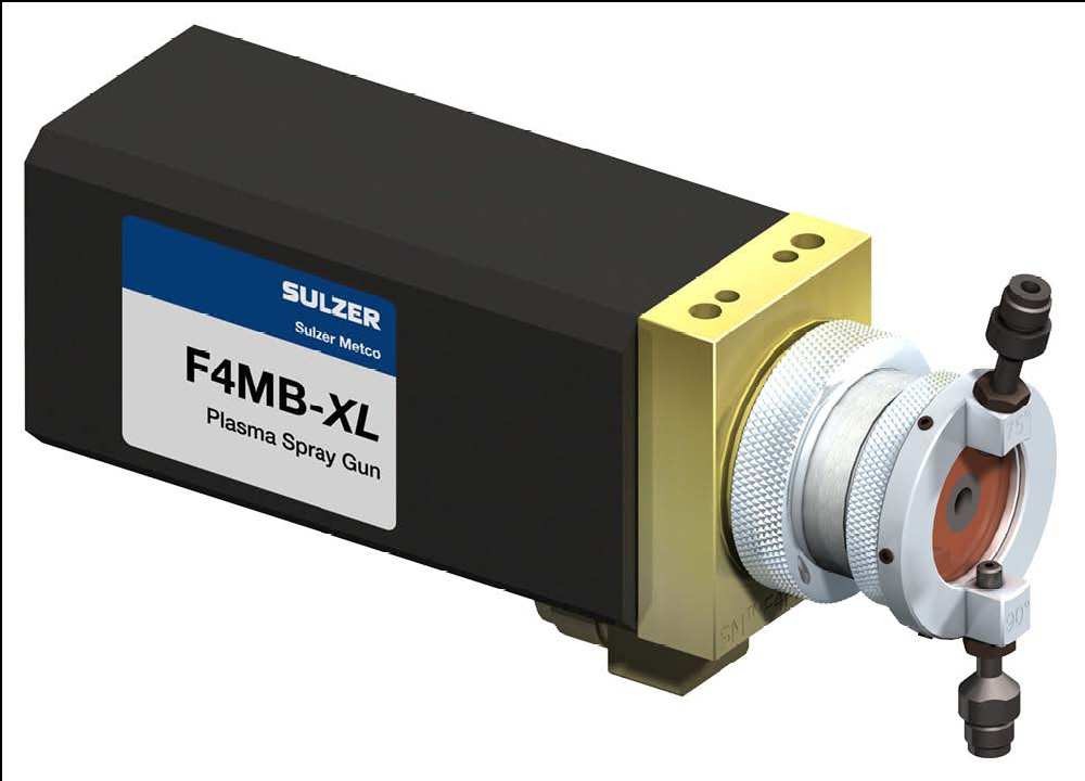
A slightly newer and more powerful (55 kW) single-cathode device is the F4 plasmatron, shown in Figure 30.
Rice. 30. Plasmatron F4.
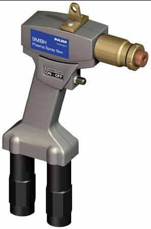
The 9MB device is one of the most powerful single-cathode plasmatrons of the traditional type (80 kW at a current of 1000 A and a voltage of 80 V) also produced by Sulzer Metco (Figure 31):
Rice. 31. Plasmatron 9MB

Traditional single-cathode plasmatrons from other companies differ little from Sulzer Metco plasmatrons: they all operate at a relatively low gas flow rate, low (< 100 В) напряжении и большом (до 1000 А) токе дуги. Ни один из традиционных плазматронов не позволяет достичь частицам скорости звука.
The advantage of plasmatrons with a low gas flow rate is the ability to impart a very high temperature to the particles (> 4000°C) due to the relatively long time they remain in the hot zone of the flame next to the arc. Such high particle temperatures make it possible to melt almost any ceramic and metal materials.
The development of plasma spraying technology in the last twenty years has been moving along the path of increasing particle speed. To give the particles greater speed, it is necessary to increase the pressure of the plasma-forming gases in front of the nozzle, which automatically leads to an increase in gas flow and an increase in arc voltage.
A modern, powerful (up to 85 kW, current up to 379 A, voltage up to 223 V) device with one cathode and anode is the 100HE plasmatron American company Progressive Technologies Inc., which, thanks to the high pressure and flow rate of plasma-forming gases, makes it possible to achieve particle speeds close to the speed of sound (Figure 32):
Rice. 32. Plasmatron 100HE.

Due to the high speed of the plasma-forming gas, the residence time of particles in the hot zone of the flame and, accordingly, their temperature decreases. To counteract this, it is necessary to increase the arc power and use it in plasma-forming gas a large number of hydrogen, which, thanks to the process of dissociation-association of molecules, lengthens the hot zone of the flame. Thus, the 100HE plasmatron realizes the temperature of particles with a size of 20-30 microns above 2300°C at a speed of about 250 m/sec, which makes it possible to spray coatings of Cr 3 C 2 - NiCr, Cr 2 O 3 and Al 2 O 3 with low porosity.
The second direction of development, in combination with an increase in gas consumption, is the division of one arc into three parts, which improves the stability and uniformity of the flame, reduces wear of the electrodes and increases the total flame power. A typical example of such a device is the latest TriplexPro TM -210 plasmatron from Sulzer Metco with one anode and three cathodes, a maximum power of 100 kW (Figure 33):
Rice. 33. Plasmatron TriplexPro TM.

1 – rear part of the body; 2 – anode stack; 3 – front part of the body; 4 – insulator; 5 – union nut; 6 – three cathodes in a ceramic block; 7 – anode stack element; 8 – plasma channel; 9 – nozzle with three powder nozzles.
Sulzer Metco's Triplex technology entered the thermal spray industry in the 1990s. These devices have, in comparison with plasmatrons with a single arc, a significantly longer service life and stability of deposition results. For many commercial powders, Triplex plasmatrons can also improve spraying productivity and efficiency while maintaining coating quality.
GTV GmbH has released, bypassing the Sulzer Metco patent for three-cathode plasmatrons, the GTV Delta device with one cathode and three anodes, which, in principle, is a degraded compilation of TriplexPro (Figure 34):
Rice. 34. GTV Delta plasmatron.


The last, third direction of development is the abandonment of radial powder input in favor of a much more rational one - axial. The key design element of a plasmatron with axial powder injection, Convergens, was invented in 1994 by the American Lucian Bogdan Delcea.
Currently, there is only one similar device - the Axial III plasmatron, with a maximum power of 150 kW, produced by the Canadian company Mettech, which combines all three directions of development (high gas flow, three arcs and axial powder input). Plasma spraying units with the Axial III plasmatron are also manufactured and distributed by the German company Thermico GmbH.
Figures 35, 36 and 37 show the Axial III device itself and its design diagram:
Rice. 35. Plasmatron Axial III.

Rice. 36. View of the Axial III device from the nozzle side.

 Rice. 37. Schematic diagram Axial III.
All modern plasma spraying installations are automatic, that is, the control of current sources, water cooling system and gas flow is regulated by a CNC system with visualization and saving of recipes on a computer. For example, the Axial III plasmatron is supplied by Thermico GmbH complete with a computerized control system that independently ignites arcs and enters the operating mode, selects spraying recipes, and controls all the main parameters: the flow of three plasma-forming gases (argon, nitrogen and hydrogen) , arc currents, parameters of the water cooling system. This same automatic system also controls the powder feeder.
Special mention needs to be made about the Thermico powder feeder. This, the most “advanced” device in the world today, allows not only to constantly regulate the mass flow of the powder and the flow of the carrier gas (nitrogen or argon), but also allows the use of fine-grained powders with poor flowability, unsuitable, for example, for Sulzer Metco feeders.
The author has personally worked with the Axial III plasmatron for a long time and can say from his own experience that despite some design flaws, this plasmatron is the most advanced thermal spraying device, combining the advantages of high-speed spraying with a high temperature strictly reducing flame. The main advantage of Axial III is the axial input of powder.
Axial powder injection is a quantum leap in plasma spraying technology. The point here is not only that with axial input, powder losses are significantly reduced, but also that the possibility of spraying completely different powder materials that are unsuitable for radial input opens up. Since this aspect is fundamentally important for understanding the following sections, we will dwell on it in more detail.
So, what happens when powder is radially introduced into the flame jet at the nozzle exit? We list the disadvantages of such input:
Switching to axial injection of powder allows you to completely get rid of the above problems:
The author was very fortunate to have had an Axial III plasmatron with axial powder injection at his disposal for many years. If not for this, the creation of new multicomponent coatings would simply be impossible.
To generalize, directly compare and systematize all thermal spraying methods, let’s compare the properties of typical devices, as well as their approximate prices in one table (Table 2):
Table 2. Comparison of Thermal Spray Devices.
| Properties and characteristics | * Thermal spray methods | |||||||
| 1 | 2 | 3 | 4 | 5 | 6 | 7 | 8 | |
| Using powder or wire | wire | powder | wire | powder | powder | powder | wire | powder |
| Maximum speed sprayed particles, m/sec | 100 | 50 | 200 | 800 | 1200 | 1000 | 100 | 400 |
| Maximum temperature sprayed particles, °C | 2800 | 2500 | 1700 | 1500 | 600 | 1200 | > 4000 | > 4000 |
| Size of particles forming coating, microns | 0,1 – 1000 | 10 – 150 | 0,1 – 1000 | 10 – 100 | 10 – 100 | 10 – 100 | 0,1 – 1000 | 1 – 50 |
| Spraying efficiency by sprayed material | — | + | — | +++ | +++ | +++ | — | ++ |
| Spraying efficiency by flow rate | – | +++ | — | — | — | — | ++ | – |
| Minimum porosity coating, vol.% | 10-15 | 10-25 | 5-10 | 2-3 | < 1 | < 1 | 5-10 | 0,5-3 |
| Thermal power devices, kW | 10-30 | 10-50 | 30-100 | 50-250 | 30-85 | < 20 | 20-150 | 25-150 |
| Performance spraying, kg/hour | 2-5 | 5-10 | 2-5 | 5-10 | 10-20 | < 1 | 10-30 | 2-5 |
| Prevalence commercial devices and spare parts on the world market | A lot of devices | A lot of devices | Few devices | A lot of devices | Few devices | No devices | A lot of devices | A lot of devices |
| Device mobility | +++ | +++ | – | – | +++ for - for others | — | +++ | – for APS |
| Device noise | — | +++ | — | — | — | — | — | — |
| Emission of vapors and fine dust | — | ++ | — | ++ | +++ | ++ | — | – |
| Price of individual devices, € | 2.000- | 2.000- | 10.000- | 10.000- | 10.000- | No | 10.000- | 5.000- |
| Price of automated installations without peripherals, € | No | 30.000- | No | 100.000- | 100.000- | No | No | 100.000- |
| Price of automated installations with periphery “under key": soundproof cabin, filter-ventilation installation, robot, etc., € | No | 100.000- | No | 200.000- | 200.000- | No | No | 200.000- |
| Comparative Cost operation taking into account consumables materials (except powders and wires), device life and spare parts, | 10-15 | 5-15 | 30-60 | 40-100 | 40-100 | > 100 | 5-30 | 30-150 |
* Numbering of methods:
Plasma spraying based on the use of plasma jet energy for both heating and transfer of metal particles. A plasma jet is produced by blowing a plasma-forming gas through an electric arc and compressing the walls of a copper water-cooled nozzle.
Plasma coatings have the following properties: heat resistance, heat and erosion resistance, thermal and electrical insulation, anti-seize, corrosion resistance, cavitation protection, semiconductor, magnetic, etc.
Areas of application of plasma coatings: rocket, aviation and space technology, mechanical engineering, energy (including nuclear), metallurgy, chemistry, oil and coal industries, transport, electronics, radio and instrument engineering, materials science, construction, machine repair and restoration of parts.
If the cost of flame spraying with wire materials is taken as one, then the cost of plasma and flame spraying of powders will be 1.9 and 1.6, respectively, and electric arc spraying will be 0.85.

The plasma jet is produced in a plasma torch, the main parts of which (Fig. 3.34) are the electrode-cathode /, a water-cooled copper nozzle-anode 4, a steel housing 2, devices for supplying water 3, powder 5 and gas 6. Parts of the housing interacting with the cathode or anode, isolated from each other.
Powdered material is supplied to the feeder using a transport gas. It is possible to introduce powder with plasma-forming gas.
The sprayed material (powder, wire, cord, or a combination thereof) is introduced into the plasma torch nozzle below the anode spot, into the plasma arc column or plasma jet.
High temperatures and jet speeds make it possible to spray coatings from any materials that do not dissociate when heated, without restrictions on the melting temperature. Plasma spraying produces coatings of metals and alloys, oxides, carbides, borides, nitrides and composite materials.
Required physical and mechanical properties coatings are explained by the high temperature of the plasma and its flow rate, the use of inert plasma-forming gases, and the possibility of regulating the aerodynamic conditions for the formation of a metal-plasma jet.
There are no structural transformations in the material of the part; it is possible to apply refractory materials and multilayer coatings from various materials in combination of dense and hard lower layers with porous and soft upper layers (to improve the running-in properties of coatings), the wear resistance of the coatings is high, and full automation of the process is achievable.

When alloying through a wire, surfacing is carried out using high-carbon or alloyed wire under fused flux. At the same time, they are provided high accuracy alloying and stability of the chemical composition of the deposited metal over the coating depth.
Alloying of the deposited metal through flux is performed by surfacing with low-carbon wire under a layer of ceramic flux. The high hardness of the coatings excludes their subsequent heat treatment. However, this doping method was not found wide application due to the large unevenness of the deposited metal in chemical composition and the need to strictly maintain the surfacing regime.
The combined method of alloying simultaneously through wire and flux has become most widespread.
Rectifiers VS-300, VDU-504, VS-600, VDG-301 and converters PSG-500 with a flat-sloping or rigid external characteristic are used as power sources. Special installations are used as part rotators (UD-133, UD-140, UD-143, UD-144, UD-209, UD-233, UD-299, UD-302, UD-651, OKS-11200, OKS- 11236, OKS-11238, OKS-14408, OKS-27432, 011-1-00 RD) or decommissioned turning or milling machines. For wire feeding, heads A-580M, OKS-1252M, A-765, A-1197 are used.
The main technological parameters of surfacing: composition of the electrode material and flux, arc voltage U, current strength / and polarity, surfacing speed vH and feed vn of the electrode material, surfacing pitch S, electrode displacement from the zenith e, diameter d3 and electrode stickout. Approximate modes of surfacing under a layer of flux cylindrical parts are given in table. 3.52.
Surfacing under a layer of flux has the following varieties.
Surfacing with a lying electrode (rod or plate) made of low-carbon or alloy steel is used to restore planes. Part of the flux is poured onto the surface to be restored (3...5 mm thick), and part - onto the electrode (the thickness of the flux layer reaches 10... 15 mm). Flux mixtures are used. In one place, the electrode is connected to a part to excite an arc, which, when burning, wanders in the transverse direction. The current density is 6...9 A/mm voltage 35...45 V. To carry out the process there is an OKS-11240 GosNITI installation.
Increased productivity and a higher content of alloying elements in the coating are provided by multi-electrode submerged arc surfacing on parts with significant wear over a large area (Fig. 3.23). A stray arc burns between the part and the electrode closest to it.
Trapping a layer of powder (6...9 mm thick) under a flux increases the productivity of the process and ensures the production of thick coatings of the desired composition.
The scope of application of mechanized surfacing with a layer of flux extends to the restoration of parts (with a diameter of more than 50 mm) made of carbon and low-alloy steels, requiring the application of a layer thickness > 2 mm with high requirements to its physical and mechanical properties. Shaft journals, surfaces of rollers and rollers, bed guides and other elements are fused.
Mechanized surfacing under a layer of flux has the following advantages:
— an increase in labor productivity by 6...8 times compared to manual electric arc surfacing with a simultaneous reduction in energy consumption by 2 times due to higher thermal efficiency;
— high quality deposited metal due to saturation with the necessary alloying elements and rational organization of thermal processes;
— the ability to obtain coatings with a thickness > 2 mm/p.
Argon, helium, nitrogen, hydrogen and their mixtures are used as plasma-forming gases when spraying materials (Table 3.68). Plasma-forming gases do not contain oxygen, therefore they do not oxidize the material and the sprayed surface.
Helium and hydrogen in their pure form are practically not used for economic reasons, as well as due to the destructive effect on the electrode.
Nitrogen and argon are used more often, but gas mixtures, for example Ar + N, and Ar + H2, have the best performance. The type of plasma-forming gas is selected based on the required temperature, heat content and flow rate, its degree of inertness to the sprayed material and the surface being restored. It should be taken into account that the plasma of di- and polyatomic gases, compared to monatomic gases, contains more heat at the same temperature, because its enthalpy is determined by the thermal motion of atoms, ionization and dissociation energy.
When spraying powder or cord materials, electrical voltage is applied to the electrodes of the plasma torch. When spraying wire materials, voltage is applied to the burner electrodes; in addition, it can be applied to the sprayed material, i.e. the wire may be current-carrying or not. The sprayed part is not included in the load circuit.
Powders for plasma spraying should not create blockages in transport pipelines, but should be uniformly fed into the plasma stream and move freely with the gas flow. These requirements are met by spherical powder particles with a diameter of 20...100 microns.
At the Institute of Electric Welding named after. E.O. Paton NAS of Ukraine developed flux-cored wires. AMOTEC. consisting of a steel shell and powder filler. These materials are intended for applying wear- and corrosion-resistant coatings using gas-flame, electric arc and plasma spraying. A special feature of the materials is the possibility of amorphizing the structure of sprayed coatings. The presence of an amorphous component in the structure of coatings provides a complex of increased service properties (wear and corrosion resistance, strength of connection with the base).
To protect particles of the sprayed material from oxidation, decarburization and nitriding, gas lenses (annular flow of inert gas), which are like a shell of a plasma jet, and special chambers with an inert environment in which the spraying process takes place are used.
Let us give examples of the use of plasma spraying in the processes of restoring parts.
Several varieties of the process of restoring the main supports of cylinder blocks have been mastered. The first researchers of the method recommended low-carbon steel wire Sv-08 as the applied material to ensure a uniform, finely dispersed structure of the coating and increase the strength of its connection to the base. Later, powdered materials were recommended. Composite powders and bronze powders have become widespread. Bronze powders are applied to the surfaces of both cast iron parts and parts made of aluminum alloy. A thermoresponsive Al-Ni sublayer must first be applied.
When restoring the main bearings in cast iron cylinder blocks, a cheaper powder with a granulation of 160...200 microns of the composition: Fe (base) is used. 5% Si and 1% AI. Coating mode: plasma arc current 330 A, voltage 70 V, plasma gas (nitrogen) flow rate 25 l/min, plasma torch nozzle diameter 5.5 mm, plasma torch oscillation frequency 83 min', part feed 320 mm/min, powder consumption 7 kg/h.
The process of applying plasma coating to the surfaces of holes in aluminum alloy parts includes:
1) drying powders at a temperature of 150..20 °C for 3 hours;
2) preliminary boring of holes to a size exceeding 1 mm nominal size holes;
3) installation of protective screens;
4) degreasing the sprayed surfaces with acetone;
5) coating in two operations;
6) removal of protective screens;
7) preliminary and final boring;
8) flash removal.
In the first operation, a sublayer of PN-85Yu15 is applied, in the second, a main layer of PMS-N copper powder is applied. Coating application modes: current 220...280 A, nitrogen flow 20...25 l/min at a pressure of 0.35 MPa. distance from the nozzle to the part is 100... 120 mm, coating time is 15 minutes. The coating is applied on a stand. Plasma-forming equipment consists of a power source IPN 160/600 n installation UPU-ZD or UPU-8.
Plasma spraying is used to apply coatings to the planes of silumin cylinder heads. The technology includes preliminary milling of the worn surface, coating and subsequent processing. Aluminum powder and 40...48% Fe are used as coating materials. Coating mode: current 280 A, distance from nozzle to part 90 mm. consumption of plasma-forming gas (nitrogen) 72 l/min.
In order to reduce the cost of the process and increase its productivity, the process of electric arc spraying of planes from Sv-AK5 wire with a diameter of 2 mm was introduced. A VGD-301 current source and an EM-12 metallizer are used. Spraying modes: current 300 A, voltage 28... 32 V, spray air pressure 0.4...0.6 MPa, distance from nozzle to part 80... 100 mm. A coating 5 mm thick is applied in 8... 10 minutes.
When restoring aluminum alloy pistons, a plasma coating of PR-Br bronze powder is applied. AZHNMts 8.5-4-5-1.5 (8.5% AI, 4% Fe, 4.8% Ni. 1.4% Mn, the rest Cu). They use the UPU-8 installation. Application mode: current 380 A, distance from nozzle to part 120 mm. plasma-forming gas is a mixture of argon and nitrogen.
When restoring crankshafts made of high-strength cast iron, a plasma coating from a composition of powders is applied to a thermoresponsive base made of PN-85Yu15 material. Composition: 50% PGSR, 30% PZh4 and 20% PN85Yu15.
Process modes: I = 400 A, distance from nozzle to workpiece 150 mm. nitrogen flow 25 l/min. According to the author's certificate for the invention of the USSR No. 1737017, the purpose of which is to increase the adhesive and cohesive strength of coatings, the applied material contains (in wt. %): a self-fluxing alloy of the Ni-Cr-B-Si system 25...50, iron powder 30...50 and nickel -aluminum powder 20…25.
Microplasma spraying is used when restoring parts of parts with dimensions of 5... 10 mm in order to reduce losses of sprayed material. Low power plasmatrons are used (up to 2...2.5 kW), generating a quasilaminar plasma jet at a current strength of 10...60 A. Argon is used as a plasma-forming and shielding gas. With microplasma spraying, it is possible to reduce the diameter of the metal-plasma jet to 1...5 mm. The process is characterized by a low noise level (30...50 dB) and a small amount of exhaust gases, which allows spraying to be carried out indoors without the use of a working chamber. The MPN-001 microplasma spraying installation has been created.
Technological modes of plasma spraying are determined by: the type and dispersion of the material, the current of the plasma jet and its voltage, the type and flow rate of the plasma-forming gas, the diameter of the plasma torch nozzle and the distance from the nozzle to the sprayed surface.
The dispersion of material particles, the current of the plasma jet and the flow rate of the plasma-forming gas determine the heating temperature of the particles and their speed of movement, and therefore the density and structure of the coating.
Greater uniformity of coating properties is ensured at a higher speed of movement of the plasma torch relative to the part and a smaller layer thickness. This speed has little effect on the material utilization rate and has a significant impact on the productivity of the process.
The distance from the nozzle to the surface to be restored depends on the type of plasma-forming gas, the properties of the sprayed material and varies within 120...250 mm (usually 120...150 mm). The angle between the axis of the particle flow and the surface to be restored should approach 90°.
The optimal combination of the heat content of the plasma flow, the residence time of particles in this flow and their speed ensures the production of coatings with high physical and mechanical properties.
The properties of plasma coatings are significantly improved when they are melted. In this case, the most fusible part of the material melts, but the heating temperature must be sufficient to melt borosilicates, which reduce metals from oxides and form slags.
The materials to be melted must meet the following requirements: the melting temperature of the low-melting component of the alloy should not exceed 1000... 1100 °C. The alloy in a heated state should well wet the surface of the workpiece and have the property of self-fluxing. Nickel-based powder materials having a melting point of 980...1050 °C and containing fluxing elements: boron and silicon have such properties. Insufficient heating temperature of the coating leads to the formation of metal drops on the surface. Liquid state part of the coating promotes intensive diffusion processes, while the material of the part remains in a solid state.
As a result of melting, the strength of the connection between the coating and the base significantly increases, cohesive strength increases, porosity disappears and wear resistance improves.
Melted coatings have machinability close to that of monolithic heat-resistant steels and alloys of similar chemical composition.
The coatings are melted: with a gas burner (oxy-acetylene flame), in a thermal oven, with an inductor (currents high frequency), an electron or laser beam, a plasma torch (plasma jet), passing a large current.
Reflowing with a gas torch is the simplest method that allows you to visually control the quality of reflow. The disadvantages of this method are one-sided heating of the part, which can lead to warping, and greater labor intensity when processing massive parts.
Furnace melting ensures heating of the entire volume of the part, so the likelihood of cracks is reduced. However, the areas of the part adjacent to the coating become covered with scale, and their physical and mechanical properties deteriorate. The negative influence of an oxidizing atmosphere on the properties of coatings when heated is eliminated in the presence of a protective environment.
Good results are obtained by induction reflowing, which provides greater productivity without disrupting the heat treatment of the entire workpiece. Only the coating and the adjacent thin layer of base metal are subjected to heating. The thickness of the heated metal depends on the frequency of the current: as the latter increases, the thickness decreases. High speeds heating and cooling can cause cracks in the coating.
Melting coatings with an electron or laser beam practically does not change the properties of the areas adjacent to the coating and the core of the part. Due to their high cost, these methods should be used when restoring critical, expensive parts whose coatings are difficult to melt using other methods.
Melted coatings made of nickel-based alloys PG-SR2. PG-SRZ and PG-SR4 have the following properties:
— hardness 35...60 HRC depending on the boron content;
— wear resistance increased by 2...3 times compared to hardened steel 45, which is explained by the presence of hard crystals (borides and carbides) in the coating structure;
— the strength of the connection between the coating and the base is increased by 8...10 times compared to the strength of the connection of unfused coatings;
— increased fatigue strength by 20...25%.
The area of application of plasma coatings with subsequent melting is the restoration of the surfaces of parts operating under conditions of alternating and contact loads.
Melted coatings have a multiphase structure, the components of which are borides, excess carbides and eutectic. The type of microstructure (dispersity, type and number of components) depends on the chemical composition of the self-fluxing alloy, heating time and temperature.
The best wear resistance of parts in loaded joints is provided by coatings made of self-fluxing alloys. The structure of the coating is a highly alloyed solid solution with inclusions of dispersed metal-like phases (primarily boride or carbide) with a particle size of 1...10 microns, uniformly distributed in the base.
For plasma spraying of metal and non-metallic coatings (refractory, wear-resistant, corrosion-resistant), the following installations are used: UN-115, UN-120, UPM-6. UPU-ZD. UPS-301. APR-403. UPRP-201.
Gas flame spraying Vacuum Condensation Spray Process Vibration arc surfacing Application of wear-resistant corrosion-resistant coatings on cast parts of machines, mechanisms and technological equipment
Plasma surfacing is an innovative method of applying special coatings with a high wear resistance to the surface of worn products. It is performed to restore machine parts and mechanisms, as well as during their production.
A number of components and mechanisms of various devices and machines today operate in difficult conditions that require products to meet several requirements at once. They are often required to withstand the influence of aggressive chemical environments and elevated temperatures, and at the same time maintain their high strength characteristics.
It is almost impossible to make such units from any one metal or other material. And from a financial point of view, it is not practical to implement such a complex production process.
It is much more reasonable and profitable to produce such products from one, maximum durable material, and then apply certain protective coatings to them - wear-resistant, heat-resistant, acid-resistant, and so on.
As such “protection”, you can use non-metallic and metallic coatings, which differ from each other in their composition. Such spraying makes it possible to give products the necessary dielectric, thermal, physical and other characteristics. One of the most effective and at the same time universal modern methods of coating materials with a protective layer is spraying and surfacing with a plasma arc.
The essence of using plasma is quite simple. For coating, material is used in the form of wire or granulated fine powder, which is fed into a plasma jet, where it is first heated and then melted. It is in the molten state that the protective material ends up on the part undergoing surfacing. At the same time, its continuous heating occurs.
The advantages of this technology are:
Based on this, we can conclude that neither vacuum, nor galvanic, nor any other spraying option can be compared in its effectiveness with plasma. Most often it is used for:

Plasma surfacing of metal is performed using two technologies:

The plasma jet can have different configurations. According to this indicator, it is divided into three types:

For any arrangement, the gases used to form the flame are oxygen, argon, air, helium, hydrogen or nitrogen. Experts say that helium and argon provide the highest quality deposition and surfacing of metal.
Plasma powder surfacing on most modern enterprises carried out precisely in combined units. In them, metal filler powder is melted between a torch nozzle and a tungsten electrode. And while the arc burns between the part and the electrode, heating of the surface of the welded product begins. Due to this, high-quality and rapid fusion of the base and filler metal occurs.
The combined plasma torch ensures a low content of the deposited base material, as well as the smallest depth of its penetration. It is these facts that are recognized as the main technological advantage of surfacing using a plasma jet.

The surface to be deposited is protected from the harmful influence of ambient air by inert gas. It enters the nozzle (external) of the installation and reliably protects the arc, surrounding it. A transport gas with inert characteristics also supplies the powder mixture for the additive. It comes from a special feeder.
In general, a standard plasmatron of a combined type of action, in which metal is sprayed and surfaced, consists of the following parts:

The maximum performance of the plasma torch is observed when a current-carrying wire additive is used. The arc in this case burns between this wire (it is the anode) and the cathode of the unit. The described method slightly melts the base material. But it does not make it possible to create a uniform and thin surfacing layer.

If powder is used, spraying and surfacing make it possible to obtain the specified thin layer with maximum wear resistance and heat resistance. Typically, the components of the powder mixture for surfacing are cobalt and nickel. After using such powders, the surface of the part does not need to be further processed, since its protective layer does not have any defects.
Plasma spraying, compared to surfacing, is described by a higher plasma jet speed and a denser heat flux. This fact is due to the fact that during spraying, metals and compounds with a high level of refractoriness (borides, silicides, tantalum, carbides, tungsten, oxides of zirconium, magnesium and aluminum) are most often used.

Let us add that the surfacing method discussed in the article has its own technical specifications(range of operating voltages and currents, inert gas consumption, and so on) is not much different from. And specialists have mastered this type of welding to perfection these days.
A general indicator characterizing the use of fixed assets on...

The textbook and workshop, consisting of two parts, contains theoretical and...

The question is asked by Ildar Mullakhmetov: Nikolay, hello. Nice...