There are many different ways to become a photographer, one of them I see is to stop...


The simplest and quick way create diagrams using idef0 and idef3 graphic notations - use a freely distributed cross-platform editor for diagrams, flowcharts, network diagrams, UML diagrams and other evil spirits called "Dia". The program has been translated into many languages, including Russian.
You can download the program on its official website: http://projects.gnome.org/dia/. At the time of writing, the latest version of the Dia program was numbered 0.97.1 - and it has been such for almost two years. Despite this, the functionality of the application is excellent.
to create diagrams in the idef0 graphic notation, just select the standard library of Dia elements called "SADT / IDEF0":
If this is your first time encountering idef0, I highly recommend that you first read these articles about this methodology:
With idef3 it’s a little more complicated. There is no standard set of elements for constructing a diagram in the idef3 graphic notation in Dia, but all the necessary blocks are in the program. You just need to group them manually. To do this, click in the menu: “File -> categories and objects.” In the window that opens, click the “Create” button. Another window will open, in which we select the “Category Name” item and enter “idef3” there. The process of creating a category looks something like this:
Since you just created this category, naturally it is empty. We need to move the necessary circuit elements into it. That's why:

Click the "Apply" button, "Close" the window and you're done! We go to “other element libraries” and select the graphic notation “idef3” we created there (it is located in its proper place in the alphabet). By the way, to write in blocks, it is convenient to use the F2 key. Of course, this is not a perfect tool, but this method allows you to create IDEF3 diagrams as close as possible to their exact graphical notation.
If you know other free tools for constructing diagrams in IDEF3 graphic notation, then share it with everyone in the comments.
Workshop on using IDEF0 for functional description of software
Part 1.
If we analyze advertisements for hiring employees from software development companies, then Lately There is an acute shortage of project managers capable of competently setting tasks. The problem is not that they cannot formulate the problem, but that they cannot correctly format the documentation taking into account modern design standards. The customer has alreadyIt’s not enough to give a few sheets of paper typed in Word. He wants documentation formatted in BPWin, ErWin, S-Designer, Power Designer, Rational Rose, etc. Behind each of these CASE tools is a standard. This article is devoted to one of them - IDEF0.
Introduction. When compiling documentation, each project manager considers it an “honor” to come up with something “of his own” - his own “super format” for presenting his ideas. The complexity of projects is growing, the volume of documentation for the project is growing, the documentation goes beyond working group... and then it becomes clear that the documentation does not suit the customer or the group of developers carrying out the finalization of the project and its support.
Typically, the project manager is either a great programmer (lead programmer of the project topic), or has a good command of foreign language a person familiar with programming. These are the main selection criteria for the position of project manager. This is the root of the problem. You can be a great programmer or just good employee, but this has nothing to do with the preparation of documentation.
Typically, the specification for each type of manager rolls down either to a description of the model of the program itself (the architecture of modules, classes, DLLs, the structure of the database and its use, etc.) or to a description of user functions (what they should do, what forms should be in program, etc.).
The ideal option is when the task is set by the customer. In this case, you can live by the principle “the customer wants”, and as long as he is satisfied, you receive money from the customer. But more and more projects are being created within an organization and then offered to the customer. And in this case, the quality of the documentation, what you have done and what you intend to do, comes out foreground. In this case, documentation is everything...
The IDEF0 (Integrated Definition Function Modeling) standard is intended for functional modeling and has been adopted as a US federal standard. The IDEF0 standard is one of a group of standards that are widely used to describe any business processes. Its use for describing software projects is a very young area, but using IDEF0 guarantees that your partners will take you seriously...
The application of IDEF group standards (IDEF0, IDEF1, etc.) is the actual condition for obtaining the status of an organization that satisfies ISO9000, ISO9001. These standards for an organization are an opportunity to increase product sales, an opportunity to prove that it is “on the crest of a wave.”
Many programmers widely use CASE ErWin, without knowing that it is based on the IDEF1 standard. It's not just what you like or what your customers like. This is the standard - and that's it.
Brief basic concepts of the IDEF0 standard. The IDEF0 standard is based on the concept of function. A function is a controlled action on input data, the result of which is output data, while using a certain mechanism through which this action is carried out.
The IDEF0 standard is based on three basic principles:
1. principle of functional decomposition - any function can be decomposed (detailed, broken down) into simpler functions;
2. principle of limiting complexity - the number of blocks on the diagram should be 2...6 (readability condition);
3. context principle - business process modeling begins with the construction of a context diagram, which displays only one block - the main function of the modeling system, which limits the boundary area of the modeling system (regulates First stage model building).
IDEF0 diagrams are built using blocks. Each block describes a completed action (function).
The four sides of the block have different purposes. The input data is displayed on the left, the output data on the right, the control on the top, and the mechanism on the bottom.
Input data - initial resources for the function described by the block (initial information, materials).
Output data - the resulting resources obtained as a result of the execution of the function described by the block (output information, processed source materials).
Control is what influences the process of performing the function described by the block and allows you to influence the result of the action (controls, sensors, people).
The mechanism is that by which a given action is carried out (machines, instruments, human resources, software).
The interaction between blocks is displayed as arcs (arrows). Sometimes the sides of the block are called directions, and the arrows are called flows. Arrows can be signed. The signatures are connected to the corresponding arrow using a zigzag (lightning bolt).
The general view of the implementation of the IDEF0 diagram block is shown in Fig. 1.
Fig.1. Implementation of a block used in IDEF0 diagrams.
When decomposing (detailing) a function, the newly formed diagram displays all incoming and outgoing arrows (arcs, flows) associated with the function being broken down. The number of arrows at any level of the diagram and in any direction is unlimited. The diagram is called a split block (function). Only the name of the context diagram (DC) coincides with the name of the function contained in the diagram.
In essence, diagrams form a tree. Any diagram acts as a DC in relation to the underlying ones.
As an example, consider some abstract function. This function has input data, two heterogeneous types of output data, is controlled by external influences and is implemented by mechanisms A and B. An example of the main context diagram is shown in Fig. 2, and a detailed (decomposed) version of this function, consisting of two functions (more elementary actions), shown in Fig. 3. In turn, functions 1 and 2 can also be detailed (decomposed).

Fig.2. Example of a basic diagram.

Fig.3. Example of decomposition of a main function.
The diagram is located on a special form that contains the name of the function, its graphic image, designation of the diagram with the level of nesting, connections with other functions, special information about the author, organization and the project being described.
Connections Arrows or arcs show relationships between blocks. Arrows are usually signed. Arrow signatures are chosen as nouns. For convenience, the arrows are connected to the signatures with zippers. For IDEF0 diagram readability, it is recommended to place the labels either above the arrow or to the right of the arrow.
Typically, wiring starts with data. Inputs are the data needed to execute a function. Questions rarely arise with this direction. Output is the data that is the result of executing a function. The simplest situation is when the output data is the input data for another block. Is this always the case? If the function processing input information, forms a management team, this is management. The situation is approximately the same when a function generates a data format. A data format is a mechanism for transmitting information.
The main types of connections between blocks in the diagram, formed on the basis of output information, are shown in Fig. 1.

Fig.4. Types of connections between blocks in the diagram. Accordingly, a) communication by data, b) communication by control, c) communication by mechanism, d) Feedback.
Feedback is a connection that forms a ring between blocks by data, control or format. An example of such a connection is shown in Fig. 2.d. When this connection appears, check to see if your diagram is reducible to an algorithm flowchart. The presence of such a connection is not a sign of an error.
Priority and numbering of blocks. All blocks have priority. The priority of blocks depends on the sequence of their execution. Blocks located on the left and top have the highest priority. The dominant position is horizontal.
The block numbering (block index in the diagram) in the diagram is determined based on priority. Numbering starts from one. The diagram code consists of the letter "A" and a number. DK has code A-0. The letter "A" implies active action. The diagram, which is a decomposed version of the DC, will have code A0. Each element in the A0 diagram will be coded A1 to A6 according to priority. In turn, when decomposing one of the blocks A1...A6, the block codes of the newly decomposed diagram will consist of the code of the decomposed diagram plus the index of the selected block. Chart block codes are not repeated throughout the chart.
By the number of digits in the diagram code, you can determine the level of the diagram - the level of decomposition of the DC. It is generally accepted that the recreation center is the main level, and all the others are from the first level of decomposition and higher.
Types of sequence of actions. Data can be processed sequentially or in parallel.
An example of sequential processing is filling out the address book (after all, you cannot write two addresses into it at the same time). In each block, only one instance of data is always processed, sequentially modified after each processing. The blocks are arranged either sequentially horizontally or obliquely from the upper left to the lower right.
An example of parallel processing is that you can watch TV and eat an apple at the same time. In this case, two actions are performed simultaneously. These actions are not related to each other. Such blocks in the diagram are located vertically one above the other.
Often in a diagram there is a group of actions (blocks), of which only one is performed, depending on some condition. Such actions are called alternative. For such blocks, the condition must be applied as a control action (action selection). It is recommended to introduce a special block into the diagram that processes the condition for selecting an alternative action (block). This block generates separate selection commands for each block.
The role of people in IDEF0 diagrams. What is it: control or mechanism? You decide for yourself what functions a person performs in the task being described. If the action contained in the block is controlled by a person, then control. If the action is performed through a person, then it is a mechanism. It all depends on the degree of abstraction of your problem representation.
There are cases when a person (including the same one) will act as a mechanism and control for one block. THAT HAPPENS. For example, a person writes a letter. It is written through this person, and this same person controls the content of this letter.
Control data. Management is a team. If the command contains an informative part (names, conditions, deadlines, etc.), then the informative part of the command is the input data.
The simplest solution is to divide the original arrow into two: control and data. These arrows are connected to the corresponding sides of the block. Both divided arrows must have appropriate inscriptions.
Sergey Sokolov (Minsk, BSUIR)
Email:
Open the project in which you want to create the model. If you have not created a project yet, you can use the DEMO project, which is available immediately after installing Cradle, or create your own project.
To enter the DEMO project use Username — MANAGER, password - MANAGER
How to create your own project is shown in detail in this video.
After creating a new project, you will also be able to use Username — MANAGER and password - MANAGER
To create an IDEF0 model, enable Project panel and go to the modeling section Essential Domain
Note : Similarly, you can create models in the Implementation Domain modeling section, as well as in any user-configured section. The modeling section is actually a namespace within which threads can be reused.
To create an IDEF0 context model, right-click on the IDEF0 section and select the menu items New->Element


Please note that this is the name of the entire model, not the function block on A0.
After this, the drawing area will open and you can begin creating the context model.
To do this, select the function block symbol in the palette

and click once on the workspace where you want to create the function block.
A dialog box will appear in which you must enter the name of the function block, and then click OK.

As a result, a function block with the name you specified will be created

You can select the border of a block and change its scale

To create threads, select the thread symbol in the palette (without tunneling or with tunneling)

then click on the side of the function block where you want to create a thread and click into any area of the function block

After this, a dialog box will appear for entering the name of the stream. Enter a short name for the stream and click OK
Note: You will be able to enter detailed description flow then in its specification.

After this, by analogy, you can create all the necessary threads

Save the model by pressing the floppy disk button or the CTRL+S key combination. Saving will create symbol specifications that you can edit to provide more detailed descriptions of model elements.
After saving the model, you will be able to see the created specifications in the project panel in the same section where you created the model. Two types of specifications will be created - Function and Flow.


in the dialog that appears, leave the default settings and click OK

After which a child diagram A1 will be created and all flows from diagram A0 will be transferred to it.

Now you can rename the created function block template (with a question instead of the name) and create additional ones, similar to how we created them earlier.
To rename a function block preset, select it and select Rename from the context menu

and enter the required name

By analogy, create other functional blocks corresponding to this level of decomposition

To create flows between these function blocks you need to click first on the source, then on the intermediate point to create a bend and then on the sink, for example like this:

The result is a flow with two bends

You can adjust the position of the bends by selecting the flow and dragging the bend points to the desired location

Watch the video to see it in action
To remove (or add) a bend point, press the SHIFT key on your keyboard and click at the point you want to delete or at the point in the flow where you want to create it

Save the diagram and ensure that the appropriate specifications are created

By analogy, we can decompose the functional blocks A1.
IDEF0 diagrams are built using the BPWin program. They are intended for graphical modeling of ongoing business processes
The IDEF0 methodology is widely used due to its simple and easy to understand graphical notation, the use of which for building a model is very convenient. The main place in the methodology is given to diagrams. The diagrams display the functions of the system using geometric rectangles, as well as the existing connections between the functions and the external environment. Relationships are displayed using arrows. You can see this by seeing what the IDEF0 diagram offers, examples of which can be found in this article.
The fact that the modeling uses only two graphic primitives allows us to quickly explain current rules IDEF0 interactions for those people who have no idea about it IDEF0 diagrams connect the customer to ongoing processes more quickly thanks to the use of a visual graphic language. You can see what the IDEF0 diagram offers, examples of which are presented below.

As already mentioned, 2 types of geometric primitives are used: rectangles and arrows. Rectangles represent certain processes, functions, jobs or tasks that have goals and lead to a designated result. The interaction of processes between themselves and the external environment is indicated by arrows. IDEF0 distinguishes 5 various types shooter
The IDEF0 methodology can be used to describe the functional aspect of any information system.

It is in the interests of the model to create such connections of constructions so that internal connections are as strong as possible, and external connections are as weak as possible. This strong point modeling using IDEF0. You can see examples of diagrams for yourself and see the veracity of these words. To facilitate the establishment of connections, similar ones are combined into modules. External connections are established between modules, and internal connections are established within modules. There are several types of connections.
1. Hierarchical (“part” - “whole”) connection.
2. Manager (regulating, subordinate):
2) control feedback.
3. Functional or technological:
2) reverse input.
3) consumer;
4) logical;
5) methodological or collegial;
6) resource;
7) informational;
8) temporary;
9) random.
The IDEF0 methodology provides a number of rules and recommendations for its use and improvement of the quality of use. So, the diagram displays one block on which you can specify the name of the system and its purpose. There are 2-5 arrows leading to or from the block. You can have more or less, but at least two arrows are needed for entry/exit, and the rest are for additional work and their indication on the diagram. If the arrow is more than 5, you should think about the optimal construction of the model, and whether it is possible to make it even more detailed.

Building blocks in decomposition diagrams
The number of blocks that will be on one diagram is recommended to be 3-6. If there are fewer of them, then such diagrams are unlikely to carry meaning. If the number of blocks is huge, then reading such a diagram will be very difficult, given the presence of additional arrows. To improve the perception of information, it is recommended to place blocks from top to bottom and from left to right. This arrangement will reflect the execution logic of the sequence of processes. And also the arrows will create less confusion, having minimum quantity intersections with each other.
If launch specific function is not controlled in any way, and the process can be launched at any moment, then such a situation is indicated by the absence of arrows indicating control and input. But the presence of such a situation may indicate to potential partners a certain instability and the need to take a closer look at the potential partner.
A block that only has an input arrow indicates that the process receives input parameters, but no control or adjustment occurs during execution. A block that has only a control arrow is used to indicate work that is called only by special order of the control system. They are managed and adjusted at all their stages.
But an example of constructing an IDEF0 diagram can convince you that the most complete and comprehensive type is a diagram with input and control arrows.
To improve visual perception, each block and each arrow should have its own given name, which will allow you to identify them among many other blocks and arrows. This is what example diagrams look like in IDEF0. Information system, built with the help of them, will allow you to understand all the shortcomings and complexities of the models.
Merging arrows is often used, and questions arise about their naming. But merging is only possible if homogeneous data is transferred, so separate names are not needed, although they can be specified in the BPWin program. Also, if there is a divergence of arrows, then they can be named separately in order to understand what is responsible for what.
If there is no name after the branch, then the name is considered to be exactly the same as it was before the branch. This may be the case if two blocks require the same information. The IDEF0 context diagram, an example of which can be found in this article, will confirm these words.

Arrows entering and leaving the same block when constructing a composition diagram should be displayed on it. The names of geometric figures transferred to the diagram must exactly repeat the highest level information. If two arrows are parallel to each other's arcs (i.e. they start on the edge of one process and both end on the same edge of another process), then perhaps to optimize the model they should be combined and given an appropriate name, which is perfectly displayed in IDEF0 (example diagrams in Visio can be viewed).
You have already learned what an IDEF0 diagram is, you have partially seen examples and rules for constructing such diagrams. Now we should turn to practice. For a better understanding, the explanation will not be based on some “general” model, but on specific example, which will allow you to better and more fully understand the features of working with IDEF0 in the BPWin program.
An example will be the speed of a train from point A to point B. It must be taken into account that the train cannot reach a speed greater than the permissible speed. This line is set on the basis of operating experience and the influence of compositions on railway track. It should be understood that the purpose of the train is to transport passengers, who, in turn, have paid to reach their destination safely and comfortably. An IDEF0 diagram is useful, examples of which can be found in this article.

The initial information is:
Control data:
The result of the model is:
Once the context diagram is built, it must be drilled down and then a composite diagram is created, which will be the first level diagram. It will show all the main functions of the system. The IDEF0 methodology and diagram for which the decomposition is done is called the parent. The IDEF0 decomposition is called a child decomposition.
After decomposition at the first level, decomposition at the second level is carried out - and so on until further decomposition loses its meaning. All this is done to obtain the most detailed graphic scheme ongoing and planned processes. This ready-made example IDEF0 diagrams, which you can use to navigate right now.
The abbreviation IDEF0, known today not only in narrow circles, is the first methodology that standardizes work on business processes. It was developed in the middle of the last century as part of an aerospace project in the USA and, having shown its effectiveness, became federal standard. In our country, in 2000, a document was prepared “ Functional modeling methodology IDEF0. Guidance document Functional Modeling Methodology IDEF0 Guidance Document. Official publication. State Standard of Russia RD IDEF0 – 2000. Developed by the Research Center CALS – Applied Logistics Technologies. Adopted and put into effect by the Decree of the State Standard of Russia in 2000, Moscow", but it was never approved as a standard. Although this did not prevent this methodology from becoming one of the most popular tools for graphical modeling of business processes in our country. In this article, I invite you to consider the IDEF0 model and evaluate the relevance of this approach at the present time.
Let's look a little at the names of the key elements of the methodology. The IDEF0 graphic standard is part of the SADT (Structured Analysis and Design Technique) methodology. IDEF is an abbreviation for ICAM Definition, and ICAM is derived from Integrated Computer Aided Manufacturing, which translates as integrated computerization of production. The SADT methodology is a whole family of 15 different models, which together should have made it possible to study the structure, parameters and characteristics of production, technical and organizational-economic systems.
IDEF0 is a functional model, which is the core of the construction of all other structures; it links together information and material flows, organizational structure, control influences and the very activities of the company. The graphical standard for modeling processes is also called notation. That is, notation is a system of requirements and rules for constructing an activity model in one form or another. Therefore, IDEF0 is appropriately called a notation that is part of the SADT methodology.
The IDEF0 notation is a fairly strict methodology that was originally developed, like technical design standards, for manual modeling. Therefore, it contains requirements for the placement of arrows, the format of all elements, the content of the information frame for the IDEF0 diagram, etc. Since the company’s activities are a complex multi-level system of actions, there are always many diagrams, and unambiguous systematization and navigation through all elements of the model is necessary. Nowadays this is done mainly by computer systems that support modeling in this notation. In Russia, the most famous and accessible systems today are AllFusion Process Modeler and Business Studio. I plan to devote separate articles to a review of these systems.
The central element of the IDEF0 model is the function, which is shown in the diagram as function block– a rectangle inside which an action is indicated in the form of a verbal noun. The action can be very different in scale - from the activities of the company in general and to specific manipulation in particular. Examples: “Production and sale of ceramic tableware” and “Applying a design to a product.”

Required Function Block Elements in IDEF0
Regardless of the scale of actions, all functions are displayed uniformly and necessarily contain 4 key flows, which are rigidly assigned to the sides of the function block:
This approach allows you to save a little on explanations in the diagrams and achieve unambiguity in the display of flows, which makes the entire model harmonious.
To build a functional model, the IDEF0 methodology requires the following rules to be observed.
The considered scheme is the “building block” of the IDEF0 approach. Functional modeling involves a gradual transition from the general to the specific through decomposition. Decomposition is “deepening” into the function under consideration, dividing it into smaller functions. Moreover, when a top-level function is presented in a generalized manner and then decomposed, it is appropriate to call it a process.
At the highest level, the company is represented as a “black box” in which certain activities take place that translate inputs into outputs. This level is usually called “,” that is, a diagram that describes the context of the company’s activities. Additionally, the context diagram displays key characteristics the entire model.
Thus, the context diagram contains in the most general form a description of the company’s activities, which are permeated by flows connecting the company with the outside world. I think we should also look at them in a little more detail.
Experience has shown that, despite the apparent simplicity and formality of this level, one often has to linger on it for a long time, since all results that are significant for the owner and the market must be reflected here. An error can lead to the creation of models that do not fulfill the business objectives. To check that meaningful flows are reflected, make sure that all 4 main types of flows are present in your diagram.
Please note that the company is an open system, and nothing appears or disappears in it. The company is only able to transform incoming flows into outgoing flows, and if it does this well, then additional cash flow(profit), reflecting in some sense the quality of the entire system.

(click to enlarge)
It's good if you highlight each of these types of flows with a different color so that you can easily distinguish the movement of resources and not miss important points. For example, you can often observe the absence of a client in the company’s flows, so work with him is based on the residual principle - the client often feels like a hindrance to company employees whose tasks are focused on processing the flow of documents.
Control arrows can be represented by only 1 type of flow - information, which can be divided into 2 subtypes. The first is documents such as:
The second is undocumented information, which most often refers to the requirements of the owners.
And finally, mechanisms - there are only 2 types of flows: equipment (material) and performers (divisions and people). There can be no documents here, just as there can be no people on the control switches!
For navigation, the model provides continuous numbering. The context diagram is numbered "A-0". In the future, each functional block receives its own number, no matter how deep the decomposition is.
After working through the flows of the context diagram, we can move on to decomposition. Moving to a lower level, as if opening a “black box”, we first see a blank sheet with arrows that have been attached to the functional block.

(click to enlarge)
And this is where functional modeling itself begins - we must understand what set of actions can connect these flows and ensure that all requirements are met. The difficulty is that there are a lot of actions in the company, and on the diagram we have the right to display no more than 9 functions, otherwise the diagram will become unreadable and therefore useless.
It is not always easy to arrange complex activities so that they remain visual, readable, and at the same time complete. Most often, they resort to dividing the entire variety of processes into main large blocks, the most significant of which are the following.
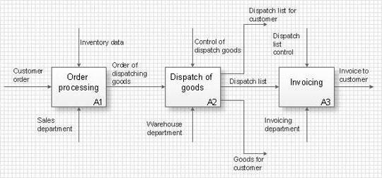
The figure below shows the decomposition diagram of our example.

(click to enlarge)
On the diagram, processes should be located diagonally - this is called the principle of dominance, which implies the arrangement of functional blocks from left to right and from top to bottom - in order of importance or in chronological order. The numbering of blocks occurs in the same way.
Further work on the model is similar to the first step - decomposition of each functional block of the first level is carried out. The numbering of blocks will contain the number of the first level: A1.1 ... A1.n, A2.1 ... A2.n, etc.
Within the framework of this article, we were able to display only the basic concepts of the IDEF0 notation using a short example of IDEF0, from which, of course, it is difficult to judge the methodology as a whole. But quite a lot of experience using this notation in practice allows me to draw the following conclusions.
Some of the above arguments lead one to think that this approach is the best and only one for complete activity simulation. But we must not forget that the functional model is designed only for the upper level of modeling. Using the IDEF0 notation to design work at the executor level leads to the fact that the diagrams are purely illustrative and it is impossible to build meaningful regulations on their basis, since they do not contain:
Therefore, if you use this notation for the tasks for which it is intended (structuring top-level activities), then IDEF0 is practically the only notation today that allows you to do this meaningfully and accurately.
IN project management this modeling standard is most applicable where it is necessary to connect different projects or processes with visual flows. The graphical model will allow for a more rational distribution of responsibility and resources among tasks. The logic for completing project tasks, reflected in the diagrams, will help prepare a better calendar plan in the form of a Gantt chart.
There are many different ways to become a photographer, one of them I see is to stop...

7 WORKING TIME AND REST TIME 7.1 Working time is considered the time during...

Although modern young people are often accused of infantilism, among them there are...